An autonomous vehicle can simultaneously have a GNSS position, a map position, a vehicle-relative position, a LiDAR coordinate frame, and a localization estimate. These are not competing answers. They are different coordinate systems describing the same physical event.
The art of HD mapping, at the lowest level, is keeping these systems in register. When they drift apart, the robot does not see an error message. It sees a world that looks correct and drives, confidently, into the wrong place.
What a coordinate system actually is
A coordinate system is an agreement. It says: we will measure position relative to this origin, along these axes, in these units, at this date. The agreement is arbitrary but it has to be shared. Every sensor, every map, and every line of planning code has to use the same agreement, or someone has to maintain a transform between the ones that do not.
At Harbor Yard, the cargo tug’s LiDAR reports positions in the sensor’s own frame, with the sensor at the origin. The map stores positions in a projected coordinate system, UTM (Universal Transverse Mercator) zone 10N, with an origin defined in 1984. The GNSS receiver reports latitude and longitude on the WGS84 (World Geodetic System 1984) ellipsoid. The planner expects everything in the map frame.
Three different coordinate systems. One robot. If the transforms between them are wrong by even a few centimeters, the tug will plan a path through a dock wall, believing it is driving through open asphalt.
The frames a robot lives in
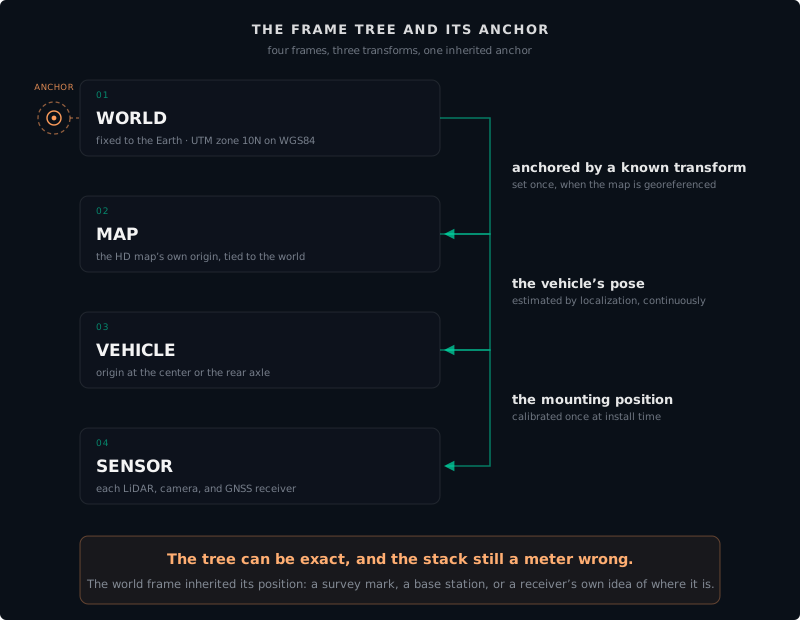
A production autonomous system typically works with four frames, nested from outermost to innermost:
World frame. The outermost reference, fixed to the Earth: a projected system like UTM, anchored to a datum like WGS84. When the site is tied to global coordinates, every other frame in the stack ultimately hangs off this one.
Map frame. The coordinate system the HD map itself is expressed in, with its own origin. That origin is arbitrary, like any capture origin: point clouds are usually built against whatever origin the scanner happened to start from, then transformed into global coordinates once. When the map is tied to global coordinates, the map origin is anchored to the world frame by a known transform, and the two frames coincide from then on. When the map is not fixed to Earth coordinates and is aligned to a local origin instead, there is no world frame above it at all: the map frame is the top of the tree.
Vehicle frame. Attached to the robot, origin at its center or rear axle. The vehicle’s pose is the transform that places the vehicle frame inside the map frame. Localization estimates this transform, continuously.
Sensor frame. Each LiDAR, camera, and GNSS receiver has its own frame with its own origin. The sensor’s mounting position, the rigid transform from sensor to vehicle frame, is calibrated once at install time and must survive vibration, temperature cycles, and the occasional bump.
The sensors feeding those frames do not speak one native geometry. A total station measures horizontal ground distances, the meters a tape would span between points. A GNSS receiver reports a position on the ellipsoid, which the software then projects into grid coordinates. A LiDAR reports ranges in its own sensor frame. Modern mapping software reconciles all of these, but only after you tell it whether the project is set to grid or to ground. Get that one setting wrong and every layer lands subtly scaled against every other, with no error message anywhere.
The frame tree stays silent about one thing: whether its anchor is right. Every transform can be exact and the stack still sits a meter from the wall, because the world frame inherited its position from whatever fixed it, a survey mark, a base station, a receiver’s own idea of where it is. Chapter 9 shows how that anchor gets set in the field; Chapter 17 shows how to find it when it is wrong.
Latitude, longitude, and why they are not enough
Latitude and longitude are the coordinate system everyone knows. They describe a position on the Earth’s surface as angles from the equator and the prime meridian.1
They are also, for most robotics work, the wrong coordinate system to compute in.
The problem is that a degree of longitude changes physical size depending on your latitude. At the equator, one degree of longitude is about 111 kilometers. At 60 degrees north, it is about 56 kilometers. A planner that computes distances in lat/lon will produce paths that stretch and compress depending on where on Earth the site is located.
The standard fix is to project: to convert latitude and longitude into a flat Cartesian coordinate system measured in meters. That is the subject of the next chapter. For now, know that lat/lon is an excellent system for recording where on Earth something is, and a poor system for computing how far apart two things are.
The local site frame
Many autonomous sites, including Harbor Yard, use a local Cartesian frame. Someone picks an origin, usually a known survey marker near the site center, and orients the axes to align with the site’s natural geometry: X along the main road, Y across it, Z up.
A local frame has several advantages. Coordinates are small numbers, easy to reason about. The Z axis points up, which matches human intuition. Distances computed in X and Y are actual meters, not degrees of arc.
For a single isolated site, aligning X with the main road works fine. But when two sites need to share a map, or a vehicle moves between them, everyone has to agree on which way the axes point. The convention is simple: X points East, Y points North, Z points up. This is called ENU (East-North-Up) and it is the standard for ground vehicles in robotics and autonomy. It is also why X coordinates are sometimes called eastings and Y coordinates are called northings.
If you work with aerial drones you will also encounter NED (North-East-Down), where the Z axis points downward because that is the direction cameras and rangefinders face during flight. ENU and NED describe the same world; converting between them is a flip and a rotation. For the rest of this Handbook, everything assumes ENU unless stated otherwise.
Grid and ground coordinates
Tie a site to a projected system like UTM and a quiet fork appears: are the coordinates grid or ground? Grid coordinates are the raw projected values. Ground coordinates are grid coordinates scaled so that distances in the data match distances measured on the earth with a tape. The two differ because flattening the earth stretches it: a 100 m distance measured on the asphalt does not measure exactly 100 m in raw UTM grid meters unless the site happens to sit on the projection’s line of exact scale. The next chapter quantifies the stretch with the combined scale factor.
Professional surveyors usually prefer ground coordinates for local work, for one practical reason: a distance in the file should be a distance a crew member can check with a tape. Grid coordinates force every field check through a scale correction first, and any check skipped is an error hidden. A local site frame, defined from a survey marker with no projection involved, is a ground system by construction. That is much of its appeal.
If you scale to ground, where you scale from matters as much as whether you do. Pick a project location, sometimes called a scaling point: a point near the center of the site and near its typical elevation. Distances are then exact at that point and drift gently outward in every direction. Scale from a corner instead, and the distortion is lopsided: near zero at the corner, largest at the far side of the site.
Bridging local and global
A flat XY grid has a deeper problem: the Earth is round, and a plane only approximates a patch of curved surface. Near the origin the fit is good, but distortion grows with distance, the same effect that makes Greenland look enormous on a Mercator map. The standard solutions are projected coordinate systems like UTM and tiling schemes like MGRS (Military Grid Reference System), which divide the world into zones small enough to keep the error in check. The next chapter covers both.
What comes next
The next chapter covers the coordinate systems most HD maps actually use: geographic systems (latitude and longitude, datums, ellipsoids, WGS84) and projected systems (UTM, State Plane, and the tools that give you meters instead of degrees). It also covers the two fields that travel with every coordinate and routinely get left off: the height reference and the date. Along the way it collects the failure modes that make coordinate mistakes the most expensive class of bug in autonomous mapping.
Footnotes
-
Geodetic coordinates are a curvilinear coordinate system defined on a reference ellipsoid. The geometry, and the conversion math to Earth-centered Cartesian coordinates, is covered on Wikipedia: Geodetic coordinates. ↩
Found an error or have a suggestion?
Report an erratum or send feedback →