A human looks at a stop line and sees paint. A robot needs to understand that same line through four distinct layers. One physical object. Four digital layers. That is not a flaw in HD mapping. It is the design.
Why there is no single map
An autonomous machine does not experience a “place.” It experiences a stream of coordinates, sensor returns, and labeled references it hopes correspond to the world. If you try to force one file to carry rough layout, precise geometry, behavioral constraints, and visual context all at once, you get a map that is too heavy to process or too sparse to trust.
Harbor Yard: one line, four layers
At the entrance to Harbor Yard, a faded white stop line crosses the pavement where the yard gate meets the main loop. Carrying that one stripe across four layers, and keeping the layers in register, is the whole job of HD mapping in miniature.
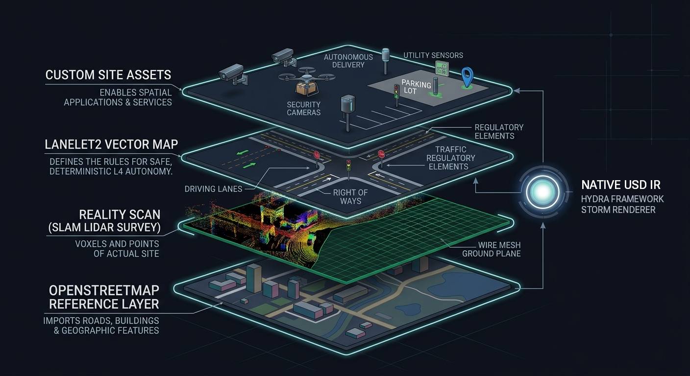
Layer 1: OSM reference (rough layout)
The OSM Ref layer gives you the basic layout of a place. Roads, buildings, geographic features, all in approximate positions. The coordinates of a curve or an intersection are not surveyor grade, but they do not need to be. This layer tells you that a road exists, that it bends left after the warehouse, that there is a gate at the south entrance. It lets you understand the road network and roughly where everything in a given geography lies.
Think of it as the sketch you would draw on a napkin for someone driving to your house. It is not a navigation system. It is not a rulebook. It is a reference. As an input to the map authoring process, it dramatically cuts down on the time needed to build a map from scratch. You are not staring at a blank canvas. You are staring at a rough but complete layout of the site, ready to be refined.
Layer 2: reality scan (captured geometry)
The reality scan is the ground truth layer. Voxels and points captured by LiDAR, structured as a dense 3D record of what is physically at the site. Unlike the OSM reference, this layer has no names, no tags, no categories. It is pure geometry.
In the reality scan, the stop line appears as a cluster of high-intensity returns. Millions of XYZ coordinates bouncing off the glass beads in the white paint. The scan tells the robot exactly where a surface is, down to centimeter precision. It provides the physical constraint. It offers zero meaning. A reality scan can tell a robot it is about to collide with something. It cannot tell it to stop for a gate.
Layer 3: vector map (behavioral constraints)
The vector map is where the stop line actually lives. It defines the “virtual tracks” in space that constrain autonomous vehicle behavior: lane boundaries, stop positions, right-of-way assignments, speed limits.
A stop line in the vector map is a regulatory element that links a position to a rule. “When you approach this coordinate, come to a complete stop. The intersecting road does not stop and has right of way.” This is where geometry meets behavior. The vector map takes the precision from the reality scan and the layout from the OSM reference, then adds the constraint that makes the robot stop.
Layer 4: custom site assets (identity and metadata)
The top layer assigns higher-level meaning to local structures. It is where a polygon stops being “a raised concrete platform” and becomes Loading Dock 1. Where an electrical panel gets an identity, Charging Station 2, with metadata for status, charge current, and last maintenance date. Where the gate becomes Gate 2, not just a barrier in the vector map.
This is the layer that enables spatial applications and services. A fleet management dashboard does not care about Lanelet2 regulatory elements. It cares that Charging Station 2 is available and Loading Dock 1 is occupied. The custom assets layer bridges the gap between the robot’s world of constraints and the operator’s world of named places with tracked state.
The image above shows all four layers composited in Veer Studio: the OSM reference in yellow, the reality scan as a dense point cloud beneath it, the vector map as colored constraint overlays, and the custom assets carrying the site-specific identities on top. The format holding that composite together is OpenUSD1: the internal representation Veer Studio uses for the multilayer map, keeping all four layers in register as one editable scene.
The four layers at a glance
| Layer | What it carries | What it gives the robot |
|---|---|---|
| OSM reference | Rough layout of roads and features | A starting point, not a survey |
| Reality scan | Precise captured geometry | Centimeter-accurate ground truth |
| Vector map | Behavioral constraints | Virtual tracks, stop positions, speed limits |
| Custom site assets | Site-specific identity and metadata | Loading Dock 1, Charging Station 2 status, Gate 2 |
The takeaway
You do not need to memorize every tag in the vector map schema yet. You need to understand that every layer in the HD map stack exists to solve a specific problem. The same physical world runs through all of them. Each layer speaks to a different listener: the sensor, the planner, the simulator, the operations dashboard.
Think of yourself as a translator for a very literal, very fast, and occasionally very confused machine. The homing pigeon on the cover has an internal compass refined by millions of years of evolution. Your robot has a LiDAR sensor and whatever file you just exported. Getting home safely means getting all four layers right, and keeping them in register with each other.
Try this
[5 min] Return to the Harbor Yard site plan at the start of Chapter 1. Pick any feature: the gate, a loading dock, the one-way loop. Name which of the four layers (OSM reference, reality scan, vector map, custom assets) handles which part of the job. If one layer is missing, what would the robot lose?
Footnotes
-
OpenUSD (Universal Scene Description) is Pixar’s open framework for assembling, composing, and versioning layered scene descriptions. https://openusd.org/ ↩
Found an error or have a suggestion?
Report an erratum or send feedback →