The previous chapter introduced coordinate frames. This one gets specific about the two families of coordinate systems you will actually encounter, how to choose between them, and how to recognize when you have chosen the wrong one. It also covers the two fields that travel with every coordinate and routinely get left off: height and date.
The shape of the Earth, approximately
The Earth is not a sphere. It is an oblate spheroid, wider at the equator than pole-to-pole, with local undulations that can deviate from the mathematical shape by tens of meters. A datum is a mathematical model of the Earth’s shape, and it is the first decision every coordinate system rests on.
WGS84 is the datum used by GNSS. It defines an ellipsoid, an origin, and an orientation. When your GNSS receiver reports a latitude and longitude, it is reporting a position on the WGS84 ellipsoid. That is a good global reference. It is not a good local working plane.
Datums have dates
WGS84 is not one fixed thing. It is a family of frames, re-anchored as measurements improved and the planet kept moving, which is why a coordinate can carry a tag like WGS84 (G1762), the GPS week that variant was aligned. North America has a second answer: NAD83 (the North American Datum of 1983), re-readjusted in 2011 into the plate-fixed frame that survey work in the United States is tied to. The two describe the same patch of ground a meter or two apart, and both are correct inside their own agreement.
The frames also move. NAD83 rides the North American plate, so a survey nail keeps its number as the plate carries it along. A frame fixed to the Earth as a whole does not, so positions in it creep past the nail by a few centimeters a year, enough to matter inside a decade.
A coordinate therefore needs a date: when it was measured, and which epoch its frame is anchored to. Leave the date off and the map does not fail, it ages. The National Geodetic Survey’s replacement for NAD83 carries an epoch on purpose, which tells you where the field is going.
The vertical equation
Chapter 5 defined the third component of the geodetic triple, ellipsoidal height h, and warned that it is not elevation. The conversion deserves its own arithmetic, because the gap is not small.
Elevation, H, known to surveyors as orthometric height, is measured from the geoid: the surface the gravity field gives mean sea level, the one water pools on and survey benchmarks are set to. The ellipsoid is the smooth mathematical surface that the geoid undulates around, sitting above it in places and below it in others. The bridge between the two is one line:
H = h - N
N is the geoid’s separation from the ellipsoid, the geoid undulation, read from a geoid model covering the site. Around Harbor Yard the geoid sits about 22 m below the ellipsoid, so a benchmark set at 12 m above sea level arrives from the receiver as -10 m. That is not a malfunction; it is the equation working.
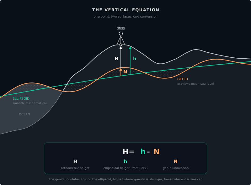
Skip the conversion and the disagreement is N, in whichever direction it was skipped. Feed raw ellipsoidal height into a frame whose Z came from survey elevations, and the vehicle sits 22 m below the pavement the cloud was captured on. Georeference the map from raw heights and convert on the vehicle side, and the vehicle floats 22 m above it.
Projected coordinate systems
A projected coordinate system flattens the curved Earth onto a plane. The result is a Cartesian grid measured in meters, which is what your planner and your vector editor actually need.
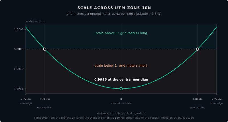
UTM, the Universal Transverse Mercator, is a common choice for outdoor autonomous sites. It divides the Earth into 60 zones, each a north-south strip 6 degrees of longitude wide, and projects each zone onto its own plane. The result is a coordinate system measured in meters instead of degrees. Distances computed in X and Y are grid distances, not ground distances, and the two differ by anywhere from zero to about 0.1 percent, depending on where in the zone you measure. That range widens toward the equator, where a zone’s edges lie farthest from the central meridian; at higher latitudes the edges sit closer in and the range stays tighter.
That 0.1 percent has a mechanical explanation, and it is worth understanding because it is the root of a whole family of map errors. Picture the projection as a surface rolled over the rounded Earth: a cylinder for UTM, a cone for many State Plane zones. Where the surface meets the ellipsoid, scale is exact. UTM’s cylinder slices slightly inside the ellipsoid, so it crosses the surface along two standard lines, the transverse equivalent of standard parallels, about 180 km either side of the central meridian: scale is exact on both lines, slightly small between them, and increasingly large outside them. Distortion is therefore zero along the two standard lines and grows with distance from them in either direction, rather than appearing at random. A projection is a smooth sheet, and its error is a smooth field across it.
Harbor Yard sits in UTM zone 10N. Every coordinate in its HD map is expressed as an easting and northing in that zone. The planner computes distances in meters. The GNSS receiver reports lat/lon, which is converted to UTM before it touches the map. One shared coordinate system, end to end.
The combined scale factor
The 0.1 percent figure is not a wall to live inside. It is a gap with a named bridge: the combined scale factor, the number surveyors use to convert between grid distances and ground distances. It is the product of two parts.
Grid factor. The distortion of the projection at your location. In UTM it is 0.9996 on the central meridian, exactly 1 on the two standard lines, and slightly above 1 near the zone edges. Read it off the zone’s distortion field for where the site sits.
Elevation factor. The distortion that comes from height. The projection is scaled to the ellipsoid, but the ground at altitude sits on a wider circle than the ellipsoid beneath it, because plumb lines converge toward the center of the Earth. A meter at elevation is a slightly longer meter in ellipsoid terms. The elevation factor accounts for the site’s height above the ellipsoid, and the effect is not exotic: roughly 1 part per million per 6 meters of height, so a site 600 m up is off by 100 ppm, 10 cm per kilometer, before the projection adds anything.
Multiply the two and you have the ratio between a grid distance and the same distance on the ground. Maps that come out subtly scaled when every datum and zone setting checks out are often this factor applied backward or not at all: going from grid to ground means dividing by the combined factor, and a workflow that skips the division quietly rescales the entire site.
Choosing a coordinate system
The decision tree is simpler than the GIS (geographic information system) textbooks make it sound:
- Is your site smaller than about 50 km across and entirely within one UTM zone? Use UTM.
- Is your site indoors or in a GNSS-denied environment? Define a local Cartesian frame tied to a fixed survey marker.
- Does your site span multiple UTM zones? You have a large site. Someone on your team has already solved this, probably with a custom local projection. Ask them.
For most controlled-environment autonomous sites, the answer is UTM. It is well-supported, globally understood, and the default in Autoware and ROS 2.
When coordinates go wrong
Coordinate failures are not subtle. They produce maps that are shifted, rotated, mirrored, scaled, or mysteriously 100 meters away from where they should be. But they are hard to diagnose because the map looks correct in isolation. A shifted map only looks wrong when you compare it to something else, like a satellite basemap, a GNSS trace, or the actual location of the robot.
Common failure modes:
Datum mismatch. The point cloud was captured in WGS84. The map was built in an editor configured for a local datum. Everything is offset by 30 to 200 meters, consistently.
Frame without a date. The map names its frame but not its epoch, the frame was anchored a decade ago, and the corrections feeding the vehicle are current. Plate motion has shifted the ground under every number by tens of centimeters, all of them equally, so the map still looks internally perfect and no longer agrees with a control point re-observed today.
Zone mismatch. The site straddles a UTM zone boundary. Half the map is in zone 10N and half in zone 11N. The join is not seamless.
Grid vs. ground mismatch. The planner expects ground distances, actual meters traveled on the asphalt, while the map carries grid coordinates, meters stretched or shrunk by the projection. Every distance in the map is off by the same fraction: near a UTM zone edge, up to about a meter per kilometer. The error is subtle and perfectly consistent, so the map looks right in every viewer. It surfaces only when a mapped distance is compared against a measured one, or when the robot’s odometry and the map disagree about how far it has driven.
Unit confusion. One tool outputs meters, another expects feet. The map is scaled by a factor of 3.28. Nothing lines up.
Axis swap. The X and Y axes are swapped. The map is rotated 90 degrees relative to reality. This happens more often than anyone wants to admit.
Altitude as height. The Z coordinate means different things in different systems: height above the ellipsoid, height above mean sea level, or height above a local reference, and the vertical equation puts a number on the gap: 22 m at Harbor Yard, in whichever direction the conversion was skipped. A robot that treats one as the other plans paths at the wrong elevation. Height also leaks into the horizontal: the elevation factor is computed from the site’s height above the ellipsoid, and what should feed it is the site’s mean elevation. On a site with significant vertical relief, a factor computed from the wrong reference elevation skews distance calculations across the entire HD map, compressing some levels and stretching others.
Before you trust a coordinate
Chapter 2’s four questions ask where the vehicle stands. These four ask what a coordinate means, and every coordinate entering the stack has to answer all of them:
- Where? The numbers: latitude and longitude, or easting and northing.
- Relative to what? The frame: the datum, and the EPSG code that names it.
- When? The date it was measured, and the epoch its frame is anchored to.
- Height above what? Ellipsoidal height or elevation, and which geoid model stands between them.
Record all four answers with the map: EPSG code, capture date, frame epoch, geoid model. A file that carries them can be transformed years later without anyone guessing. A file that does not can only be argued about.
Try this
[10 min] Pull a coordinate out of your own stack, a GNSS fix, a map origin, a lane vertex, and answer those four questions from the metadata you actually have on file. Whatever you cannot answer is what your next field visit will be about.
What comes next
Part II is complete. You know what a coordinate system is, why lat/lon is not enough for robotics, how projected systems like UTM work, what a coordinate’s height and date mean, and the failure modes that will save you weeks of debugging when you encounter them.
Part III begins the next stage of the pipeline: Capture. How do we turn physical reality into data a computer can work with? It starts with point clouds.
Found an error or have a suggestion?
Report an erratum or send feedback →